Information
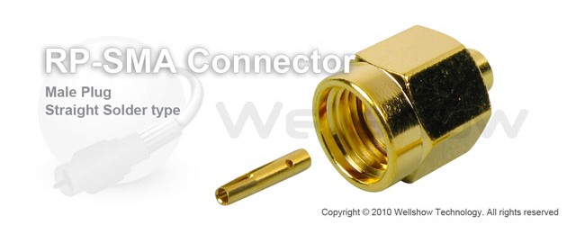
RP SMA connector is a reverse polarity SMA connector which mean SMA male body will be with female pin, or SMA female body will be with male pin.
SMA RF connector can work up to 18 GHz by soldering with low loss semi rigid or semi flex cable like .047”, RG405 (.085”) or RG402 (.141”). Such kind of high frequency but low loss SMA cable is the first choice to work as RF testing coax cable assembly for testing instrument.
RP SMA RF connector solder male has straight and right angle type (Please link here). It is 50 ohm impedance, and hex coupling nut. SMA connectors are widely used in RF various industries. If you only want commercial grade SMA cable connectors, please link the RF SMA connector main webpage to get more choices.
If you want standard SMA plug for semi rigid or semi flex cable, please link here.
If you need Right Angle RP SMA male connector for semi rigid or semi flex cable, please link here.
Part Numbers
| P/N & Drawing | Description | Cable Group | Ohm |
|---|---|---|---|
| C19AA31085004B C19AA31141004B | RP SMA straight solder plug RP SMA straight solder plug | RG405, .085”, Flexiform 405 RG402, .141” (Flexiform 402) | 50 50 |
Cable Assembly
Cable assembly Instructions Solder type
Step1. All parts of SMA RF connector are shown as the top line.
Step2. Strip the RF coaxial cable into center conductor and insulator per recommended stripping dimension shown in SMA RF connector spec.
Step3. Insert the cable inner conductor into the contact pin of SMA plug, and solder through the side hole to fix it.
Step4. Push the contact pin into the main body per SMA interface dimension.
Step5. Encircle the joint of barrel and cable by soldering.
Step6. Do the open-short test of every cable assembly before QC examination.
Specification
RP SMA Connector Technical Characteristics
| Electrical | |
| Impedance | 50 ohm |
| Frequency range | 0 ~ 18 GHz |
| VSWR | Straight type ≤ 1.3 max. |
| R/A type ≤ 1.5 max. | |
| Dielectric withstanding voltage | 1000 V rms min. for RG142, RG405 750 V rms min. for RG316, RG402 500 V rms min. for RG178 |
| Working voltage | 500 V rms max. for RG142, RG405 375 V rms max. for RG316, RG402 170 V rms max. for RG178 |
| Center contact resistance | ≤ 6.0 mΩ (Milliohms max.) |
| Outer contact resistance | ≤ 2.0 mΩ (Milliohms max.) |
| Insulation resistance | ≥ 5×10³ MΩ (Megohms min.) |
| Mechanical | |
| Coupling | 1/4-36 thread |
| Contact Retention | 15 in-lbs. min. |
| Mating torque | 2 in-lbs. min. |
| Mating Durability | 500 cycles min. (For Beryllium copper contact only) |
| Environmental | |
| Temperature Range | −65ºC ~ +155 ºC |
| Vibration | MIL-STD-202 Meth. 204 |
| Corrosion resistance | MIL-STD-202 Meth. 101 |
| Materials | |
| Body, coupling nut | Brass, Non-magnetic stainless steel |
| Insulator | Teflon |
| Center contact | Brass for male, Beryllium copper for female |
| Crimping sleeve | Annealed Brass |
| Body plating | Nickel (Ni), Gold (Au), Passivated |
| Center contact plating | Gold (Au) |
Note: These characteristics are typical and may not apply to all connectors.


